Back to GameSX.com Controller Primer Note: This page + images are free to use But please link to this page if you do! | |
|
Normally I eschew how-to guides in favour of more detailed (and more useful) pinouts and primers with which you can do anything, but here's a little change of pace for you! If you have any questions, check out this thread over on ye olde forums.
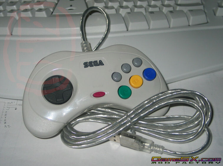
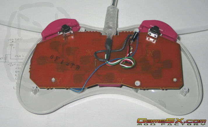
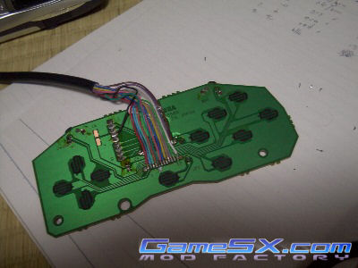
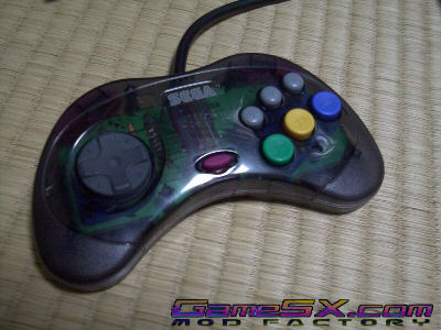
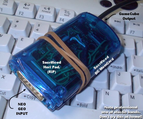
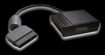
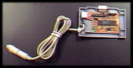
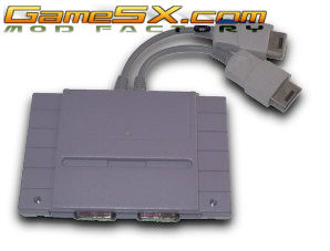
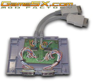
As you may have seen in the Controller Primer 2 the guts of your average controller aren't as simple as they used to be (see Controller Primer 1). Instead of one wire for each switch you've got encoding circuitry (usually a chip) in the controller reducing the number of wires needed, and the system will decode that as needed. Most controllers work this way, and in fact every post-NES system except the Neo Geo has an encoder in every controller. This makes hacking one controller to work with another system a little more difficult. You have two options: Program a microcontroller and circuit to plug into the end of your favourite controller's cable, or open it up and hack the guts making one controller permanently modded for another system. I'm a big fan of the third method, mostly because I don't know how to program microcontrollers. I gut the controller and give it a new every-button-has-a-wire cable. Since the Neo Geo has pins for as many as nine buttons it's the perfect middle ground for my purposes, and I usually add a Neo cable to my controller of choice, (Here's a Saturn Pad PCB, with new wiring job and the finished product) then make an adaptor from the controller's guts that has a Neo pad INPUT, an encoder for the console of choice, and the console's cable OUTPUT. You may recall the Neo -> GameCube adaptor I made, or the Neo -> PSX (see closeup here), or the Neo -> PC Keyboard adaptor (more here and here), or the dual Neo -> Saturn (inside) adaptor... I've been through this a few times! Dirty hacks they may be, but they work and they're decidedly low-tech - anyone who can solder can do it. In today's example I'm gonna show you how to make a Saturn pad, widely regarded as the best pad ever made ever (ever!), work with your PC, Mac or PS2 via the USB port. I've taken an off-the-shelf Elecom USB pad, removed the USB encoder chip and supporting components (two resistors, two capacitors and a crystal) and shoved them into a Saturn pad. Here's how the process works: 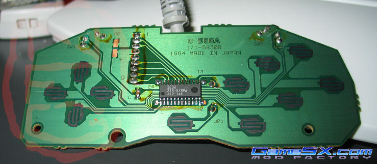 First take your Saturn pad and have a look at the inside. There's not much to it, 9 incoming wires need to be removed, and one encoder which should also be removed. Remember when this is done the Saturn controller will permanently be a USB pad, there's no going back with this mod. First take your Saturn pad and have a look at the inside. There's not much to it, 9 incoming wires need to be removed, and one encoder which should also be removed. Remember when this is done the Saturn controller will permanently be a USB pad, there's no going back with this mod.
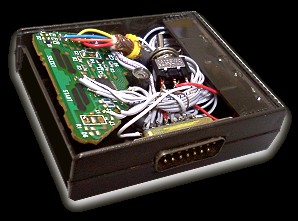
 Next have a look at your USB encoder donor's PCB. You can see here the concept is very similar; there's a common (ground) line connecting all buttons, and each button has a return line running to the chip in the center. It's a little more complicated than the Saturn pad, there's four additional components to transfer to the Saturn PCB, and the A button is tricky! It's gonna need some special attention later (you'll see). The technical bit: Where every other button is held high (+5v) by the chip until grounded (0v) by the button-press, the A button is held 'kinda high' by a resistor (R1) until the button makes it 'very high' by connecting it to +5 volts. Next have a look at your USB encoder donor's PCB. You can see here the concept is very similar; there's a common (ground) line connecting all buttons, and each button has a return line running to the chip in the center. It's a little more complicated than the Saturn pad, there's four additional components to transfer to the Saturn PCB, and the A button is tricky! It's gonna need some special attention later (you'll see). The technical bit: Where every other button is held high (+5v) by the chip until grounded (0v) by the button-press, the A button is held 'kinda high' by a resistor (R1) until the button makes it 'very high' by connecting it to +5 volts.
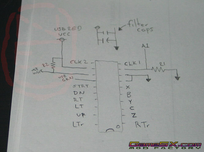 This is the schematic I made based on the USB encoding chip and components. It's a good idea to make notes as you go, in case you forget where things were after you've removed parts. I also take pictures as I go, so if my notes are wrong I've got photographic proof that I'm an idiot. You can see in this diagram half of the tricky part of A1, but what I didn't note is the other half (remember each button has two parts, and pressing them simply connects two parts) is connected directly to +5v. This is the schematic I made based on the USB encoding chip and components. It's a good idea to make notes as you go, in case you forget where things were after you've removed parts. I also take pictures as I go, so if my notes are wrong I've got photographic proof that I'm an idiot. You can see in this diagram half of the tricky part of A1, but what I didn't note is the other half (remember each button has two parts, and pressing them simply connects two parts) is connected directly to +5v.
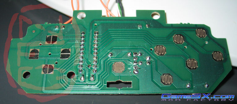
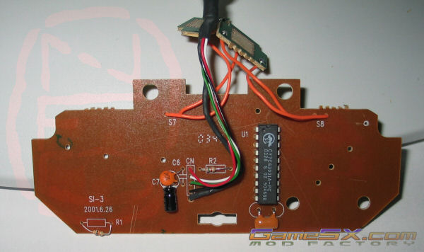 For reference this is the top side of the USB PCB. I had to rely on this picture after I removed the resistors R1 and R2 and couldn't remember which was which. I suck, I know. For reference this is the top side of the USB PCB. I had to rely on this picture after I removed the resistors R1 and R2 and couldn't remember which was which. I suck, I know.
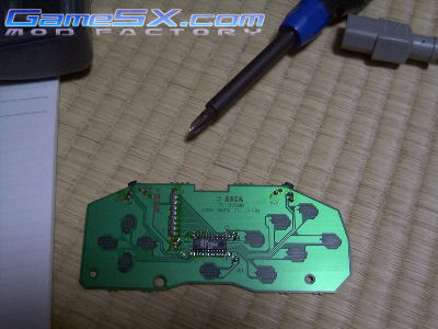
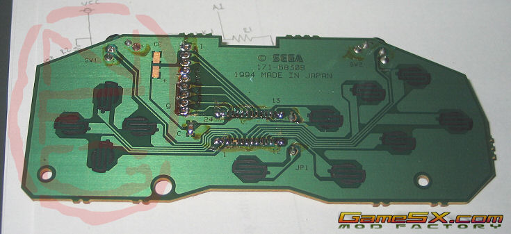 Here is the bare Saturn pad PCB. Everything's removed, and all we need to do is slap the new components in there. Sega left us lots of room right in the center for new parts, and they won't be in the way of anything. Yay for Sega - great pads and hacker-friendly. Here is the bare Saturn pad PCB. Everything's removed, and all we need to do is slap the new components in there. Sega left us lots of room right in the center for new parts, and they won't be in the way of anything. Yay for Sega - great pads and hacker-friendly.
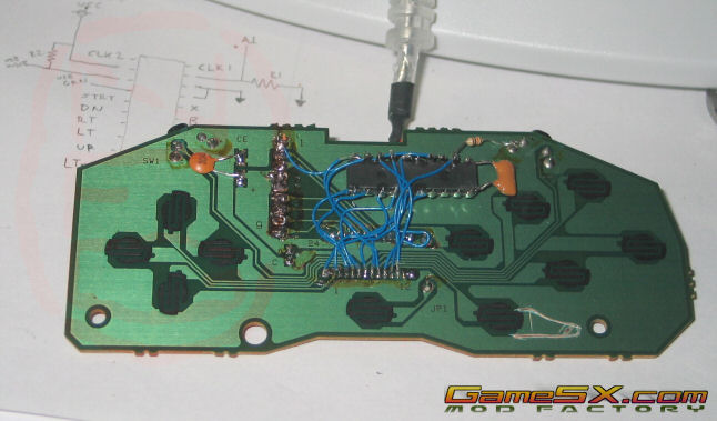
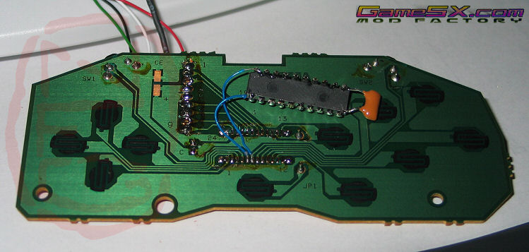 Carrying on... The first thing I did was solder the crystal directly to the chip. This eliminates a few wires and there's no reason not to do it this way. Next I attached two wires from one end of the chip to anchor it while I sized up the rest of the wires I'd need. I used solid-core wire which is fairly stiff and holds the chip in place while I work. Carrying on... The first thing I did was solder the crystal directly to the chip. This eliminates a few wires and there's no reason not to do it this way. Next I attached two wires from one end of the chip to anchor it while I sized up the rest of the wires I'd need. I used solid-core wire which is fairly stiff and holds the chip in place while I work.
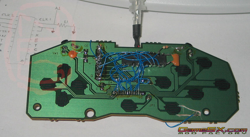
 Now we're cookin'! I've attached the USB cable, which used five wires, to the holes left where the Saturn's 9-wire cable was. I used the remaining holes for one of the filter capacitors and one of the resistors. Now we're cookin'! I've attached the USB cable, which used five wires, to the holes left where the Saturn's 9-wire cable was. I used the remaining holes for one of the filter capacitors and one of the resistors.
 You can see here I've added the other filter capacitor to two unused pads near the 9 wire holes. Thanks again, Sega, for making this so easy. I've also run the other resistor for button A to ground near the Right trigger, also conveniently located. In addition, I've isolated button A from the common ground all the other buttons share. I used an X-acto knife to make the cut, and tested to ensure its isolation using a multimeter. You definitely don't want to short +5v and GND, you'll blow fuses! There's a spot scratched off also, to connect the +5v wire. You can see here I've added the other filter capacitor to two unused pads near the 9 wire holes. Thanks again, Sega, for making this so easy. I've also run the other resistor for button A to ground near the Right trigger, also conveniently located. In addition, I've isolated button A from the common ground all the other buttons share. I used an X-acto knife to make the cut, and tested to ensure its isolation using a multimeter. You definitely don't want to short +5v and GND, you'll blow fuses! There's a spot scratched off also, to connect the +5v wire.
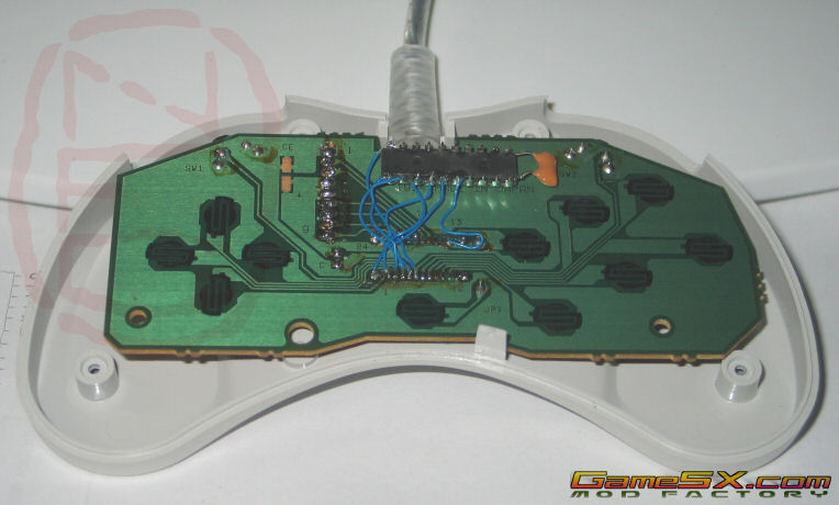
 Nearly done now! Button A's +5v wire is attached, the USB wires, Vcc and GND are all connected to the chip, and it's time to shove it into the controller shell. Nearly done now! Button A's +5v wire is attached, the USB wires, Vcc and GND are all connected to the chip, and it's time to shove it into the controller shell.
 This is how it fits: perfectly! Normally at this stage you should double-check the wiring (yeah, right) and then plug it in and test it. I skipped the checking phase and plugged it directly in - except that I forgot to put in the X button wire it worked first try. Slap that extra wire in there, close it all up and call it done. This is how it fits: perfectly! Normally at this stage you should double-check the wiring (yeah, right) and then plug it in and test it. I skipped the checking phase and plugged it directly in - except that I forgot to put in the X button wire it worked first try. Slap that extra wire in there, close it all up and call it done.
| |