
|
|
|
|
This info is based on a trace of the PC-Engine's expansion port by Joann. I have since traced it a little farther back to the chip that generates the RGB signal so the mod will work on machines without the CD-bus (Duo, PC-Shuttle etc). Opening the machine is difficult and requires special tools, see here.
This page was updated October 8th, 2004. There's new info on a better RGB amp, and alternative suggestions for AV ports. Also links to a few new pics. |
|
|
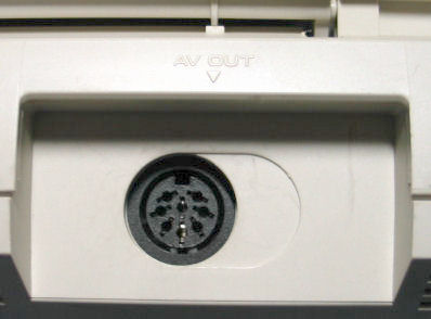
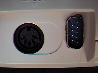
For my CoreGrafx I put a small DB-9 in front of the existing AV DIN socket. There's enough room inside the machine to allow for wires and the connector here, although you will have to cut a tiny bit of shielding. On my Duo-R I found there was enough room next to the existing A/V port for another DB-9. One preferred way to way to output RGB is by replacing the 5-pin DIN connector in most PCE hardware (Everything except the original PCE and the LaserActive, the TurboGrafx 16 and the portables) with a DIN 8. It doesn't take much work to put the DIN 8 where the DIN 5 wasm giving you RGB output without cutting new holes in the system. Have a look at this Duo R mod. Alternatively you can add a DB9 connector next to the existing AV port. There's a pic of an RGB mod to a PCE CDROM2 here (more pics).
Use caution when attaching wires to the chips, if you over-stress the legs you can break them off and then there's no RGB for anybody. You won't ruin the system, these RGB signals aren't normally used. The RGB signal obtained by tapping the chip or expansion part will lack contrast, and some monitors will protest the weak sync signal (though some will be fine with it). For best results you should amplify the RGB signal. See this image for a quality, working amp schematic. This image is taken from Backup Technique, a Japanese magazine (circa 1992). The amp that was on this page before is basically crap and shouldn't be used. My apologies. The completed amp can be as small as 4x4cm, as you can see. |
|
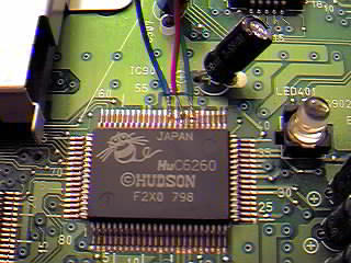
Duo R chip shown, but all PCE hardware uses the same chip. On some Duo models the chip may be under the PCB. If you need composite video instead of Sync (for example, some SCART TVs won't be happy with C-Sync) you can tap it from the AV port easily. Ground is available everywhere, it doesn't matter where you get it - as long as you do!! Note the pins: 51 - blue 49 - red 47 - green 44 - composite sync |
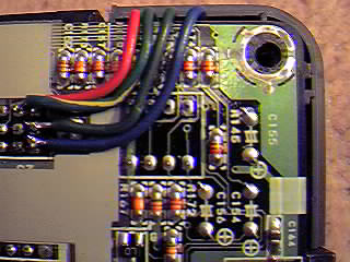
CoreGrafx shown, but all PC Engine and TurboGrafx hardware with an expansion port is identical. Please forgive the horrible picture, I'll find a better one soon. In the above picture the wires are connected to the far right pins, and are, from the bottom, red, green and blue. The second pin in on the top row is composite sync. The second in on the bottom row is composite video. Note the (im)proper expansion port numbering, looking at the bottom of the board, expansion-port up: 47........................69 24........................46 1..........................23 |
| There is enough information in the following table to make an RGB or a SCART lead for any of the non-duo machines. If your monitor connections includes an LM1881 circuit like mine do, then you won't need connect the composite sync to your output - you can simply use the video output already present. | ||||||||||||||||||||||||||||||||||||
|
* - You MUST add a 100 ohm resistor to this pin, to reduce the voltage on a SCART TV. Without it, you could find your TV will display only a blank screen. Thanks Mark K. for that.
Items marked in blue are the only pins necessary for an RGB mod, the others are for SCART only. |
|||||||||||||||||||||||||||||||||||
| Note: The following RGB amp schematic won't be necessary for everyone, but if you've got the time, parts and ability I definitely recommend it. If you're hooking your PC Engine to upscan devices like the XRGB-2 you won't need it as much. Some monitors will display an image without much contrast, and some will require at least the sync amp to display a stable picture. | ||||||||||||||||||||||||||||||||||||
![[RGB Amplifier Pic]](../grafx/pce_rgb.jpg) Click for larger |
||||||||||||||||||||||||||||||||||||
|
Finding Ground: As a general rule of thumb, any large blobs of solder holding something down will be connected to a very large metal trace running around the board, and you can use this as a grounding point. When in doubt, look at the screws. They're always connected to ground. |
||||||||||||||||||||||||||||||||||||
|
All contents (c)1997-2006 Game Station X unless otherwise noted. All trademarks copyright of their respective companies. Game Station X assumes absolutely no responsiblility whatsoever for any sort of damages incurred while either viewing this information or doing anything with said information. If you don't like it, change the channel. Some of this information may have come from other sources, and Game Station X in no way implies ownership of this information, and merely intends to provide a convenient source for finding this information. That said, we wrote this, and would appreciate your not lifting it for your own page without due credit. Mail us! |
||||||||||||||||||||||||||||||||||||