
|
|
|
|
Special thanks to Kevin Horton, whose support has been absolutely invaluable in numerous tech projects around here. Well, it turns out that the NewStyle SNES does NOT output RGB, and this mod will help you restore that capability to it. Nintendo cheaped out with the N64 too; it doesn't have RGB output either. What was surprising however was that the NewStyle SNES didn't have S-Video output either!!! We're working on it! This mod is fairly easy, although it requires a bit of planning and a steady hand. You will need to attach three wires (R, G and B) to pins 20, 22 and 24 of chip U4. The chip is clearly marked and located just behind the cartridge slot of the SNES. New! There is no Composite Sync output from the newstyle SNES. If you want to add this, you will need to run a line from pin 7 of the chip U7 to the sync output of the SNES. Thanks to Raymond Day for that little tidbit. First, remove the heatshield, then attach the three wires. Run them under where the heatshield would be, and then tuck them through a hole in the motherboard allowing them to reach the bottom of the board where we will be installing the folling components as shown in the following schematic. |
|
|
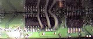
This stupidly blurry pic shows the SNES2 Chroma Encoder chip, which although is the same component on the board (U4) is NOT the same chip. This one's RGB inputs from the now integrated PPU2 chip are on different pins. The wires are run under the heatsink. You should attach the Red, Green, and Blue wires to pins 20, 22, and 24 of this chip. |
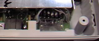
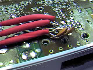
| Here you can see the wires running from the U4 Chroma Encoder under the heatsink and down through a hole in the motherboard to the underside. |
|
|
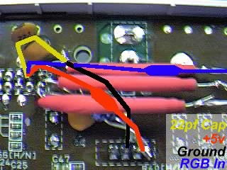
Overview of SNES2 motherboard, looking from the front to rear. Note the new RGB lines coming through the hole on the right side. |
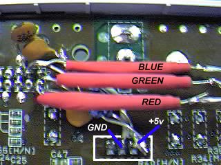
| This closeup of the circuit shows in more detail what goes where. The red tubes are resistors covered in shrinktubing to prevent shorting. The +5v and Ground wires are attached to the base of the voltage regulator. What isn't really clear here is that the wire to ground is attached to one leg of the capacitor. This is just an interference filter, and you can probably leave it out entirely. Be sure not to attach the wires to the wrong legs of the regulator!! Also I'd like to point out that this diagram only represents one of the colors, but the picture shows all three. |
|
|
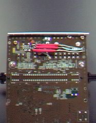
This closeup shows the completed amplifying circuit. Note the brown capacitors are bent upward - the rear of the SNES2 casing touches the rear of the board about here and they were in the way. There is sufficient depth to allow the caps to clear the bottom of the case so bend away! |
|
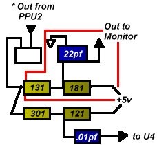
This schem shows the RGB signals' route from the PPU2
chip to the Chroma Encoder. It's not terribly clear, and I will
re-do it RSN! The Brown boxes are
resistors, the Blue ones are capacitors. My apologies
for the quality of the schem, I'm not such a wonderful
artist. The white arrow, of course, is ground, and the
large white square near PPU2 is a transistor.
Keep in mind this must be repeated for each of the R, G and B lines. This is essentially an amplifier for the outgoing RGB lines - each passes through 3 components before reaching the A/V out. The parts missing from the SNES2 are the two resistors labelled 131 and 181, and the 22pf capacitor, all of which are highlighted in red. The resistors are labelled so that the first two digits indicate the value, the third the # of zeros. So the resistor 131 is 130 Ohms, and 181 is 180 Ohms. |
|
|
All contents (c)1999 Game Station X unless otherwise noted. All trademarks copyright of their respective companies. Game Station X assumes absolutely no responsiblility whatsoever for any sort of damages incurred while either viewing this information or doing anything with said information. If you don't like it, change the channel. Some of this information may have come from other sources, and Game Station X in no way implies ownership of this information, and merely intends to provide a convenient source for finding this information. That said, we wrote this, and would appreciate your not lifting it for your own page without due credit. Mail us! | |